In order to learn and understand how radio receivers work, I am building an AM radio from an ELENCO AM radio kit. Part of the testing of the build of the kit (see here) requires you to hook up a signal generator. The signal required is a 455kHz carrier wave containing a 1kHz amplitude modulated signal. According to the kit instructions, when testing the radio IF circuit, the signal generator's IF AM signal should cause your radio kit to produce an audible tone, if you built it correctly.
After much searching and weeks of breadboarding different circuits that didn't really do what I wanted, I stumbled across a circuit in a 2008 edition of an Australian magazine called Silicon Chip (see here). The circuit is called the Minispot 455kHz Modulated Oscillator By Mauro Grassi. I assume it's free to copy as there's no copyright information on the web page. However, if you reproduce the circuit here, please acknowledge it's source.
The circuit consists of a classic relaxation oscillator using a pair of BJTs with C-R timing circuits to create an audible tone at around 450Hz. This is then fed through a third BJT where the 455kHz is mixed in from a ceramic resonator.
The ceramic resonator is a fairly common part, often used in remote controls. Strangely enough, the week I discovered the circuit, I had been given a Toshiba DVD player to repair. it was not repairable but the remote control did yield a 455kHz ceramic resonator. If you're not so fortunate to have an old remote control to cannibalize, you can easily get a bag of 10 ceramic resonators from eBay for around £2 GBP. Alternatively, try your local recycling centre - my local centre has a 'second use' shop where they re-sell many perfectly good, unwanted items. There I found TV/DVD remote controls for 50 pence each.
Circuit notes
I modified the output capacitor from the original 22pF to 27pF as that's all I had. I don't believe it has affected the functionality.
I also modified the choice of NPN BJTs from the original schematic to suit what I had available. I tried using a BC549 for Q3, but found the 450Hz modulation wasn't as clear when viewed on my oscilloscope. Swapping out for a 2N2222 (which from testing showed less gain than the BC549) made the modulation look much cleaner on my oscilloscope.
For the antenna, I grabbed a scrap 4" piece of single core wire. I calculated a proper 1/4 wave antenna for 455kHz would be in excess of 500 feet! A bit silly. I'm not sure if I should use a few feet of coiled wire instead... I guess there's insufficient output to worry about reflected signal from the end of the antenna. (I'm just a beginner so don't know much about radio antennas yet. The result of the 4" wire is that my portable Sony AM radio is tuned in to the centre of hte AM band, it screams when you hold the antenna to the back of the case - so I guess it works OK)
The circuit draws about 12mA from a PP3 9v battery. Half of that is for the LED to show it's switched on! without the LED it's more like 6.5mA. If you plan on running the circuit for long periods (I can't think of any reason why you would want to!) then leave out LED1 and R6.
As built, it produces an audible tone at around 455Hz. This is lower than I intended, but much more peasant to listen to while tuning the IF coils on your radio :) If you want to increase the frequency of the audible tone, reduce R2/C1 & R3/C2. if you want to better understand the relaxation oscillator part of the circuit, search the internet for "2 transistor oscillator", there are lots of resources that explain it clearly.
I built the circuit using copper strip board. 1.5" x 4" is plenty. You could make it more compact if you like but I wanted the component layout to be visually similar to the schematic. I think when you're learning electronics, it's worth an extra few pennies to have a layout that you can easily relate to your schematic. Troubleshooting my dodgy soldering seems to be a regular part of my learning electronics.
Copper strip board layout
The images below were created to help me visualize the layout of the schematic on copper strip board. they're here for reference if you want to use them. you could make the circuit a lot more compact, but as I previously stated, the aim was to produce a board I could easily follow with the schematic.
The circuit consists of a classic relaxation oscillator using a pair of BJTs with C-R timing circuits to create an audible tone at around 450Hz. This is then fed through a third BJT where the 455kHz is mixed in from a ceramic resonator.
The ceramic resonator is a fairly common part, often used in remote controls. Strangely enough, the week I discovered the circuit, I had been given a Toshiba DVD player to repair. it was not repairable but the remote control did yield a 455kHz ceramic resonator. If you're not so fortunate to have an old remote control to cannibalize, you can easily get a bag of 10 ceramic resonators from eBay for around £2 GBP. Alternatively, try your local recycling centre - my local centre has a 'second use' shop where they re-sell many perfectly good, unwanted items. There I found TV/DVD remote controls for 50 pence each.
Schematic
The schematic below is one I have re-drawn from the original, after breadboarding the circuit to check it worked satisfactorily. The re-draw was because I changed transistor types and capacitor values. If you click on the picture, a full size will pop up for viewing/printing.
 |
| My re-drawn schematic. A slightly modified version of the original from the Silicon Chip magazine. |
Parts list
X1 455kHz Ceramic Resonator
D1 1N4004
SW1 SPST switch
Q1,2 BC548B transistor
Q3 2N2222 transistor
LED1 5mm Red LED
R1 1.5k
R2,3 33k
R4,5 1k
R5 470R
R7 22k
R8 10M
C1,2 47nF
C3 220uF Electrolytic
C4,5 68pF
C6 27pF
extras : 9v battery, battery clip & wire for the antenna
I modified the output capacitor from the original 22pF to 27pF as that's all I had. I don't believe it has affected the functionality.
I also modified the choice of NPN BJTs from the original schematic to suit what I had available. I tried using a BC549 for Q3, but found the 450Hz modulation wasn't as clear when viewed on my oscilloscope. Swapping out for a 2N2222 (which from testing showed less gain than the BC549) made the modulation look much cleaner on my oscilloscope.
For the antenna, I grabbed a scrap 4" piece of single core wire. I calculated a proper 1/4 wave antenna for 455kHz would be in excess of 500 feet! A bit silly. I'm not sure if I should use a few feet of coiled wire instead... I guess there's insufficient output to worry about reflected signal from the end of the antenna. (I'm just a beginner so don't know much about radio antennas yet. The result of the 4" wire is that my portable Sony AM radio is tuned in to the centre of hte AM band, it screams when you hold the antenna to the back of the case - so I guess it works OK)
The circuit draws about 12mA from a PP3 9v battery. Half of that is for the LED to show it's switched on! without the LED it's more like 6.5mA. If you plan on running the circuit for long periods (I can't think of any reason why you would want to!) then leave out LED1 and R6.
As built, it produces an audible tone at around 455Hz. This is lower than I intended, but much more peasant to listen to while tuning the IF coils on your radio :) If you want to increase the frequency of the audible tone, reduce R2/C1 & R3/C2. if you want to better understand the relaxation oscillator part of the circuit, search the internet for "2 transistor oscillator", there are lots of resources that explain it clearly.
Finished circuit on copper strip board
 |
| The finished circuit powered up |
 |
| Probing the signal output Note I laid out the circuit to be visually similar to the schematic. Q3 and the 455kHz crystal are at underneath the relaxation oscillator part of the circuit. |
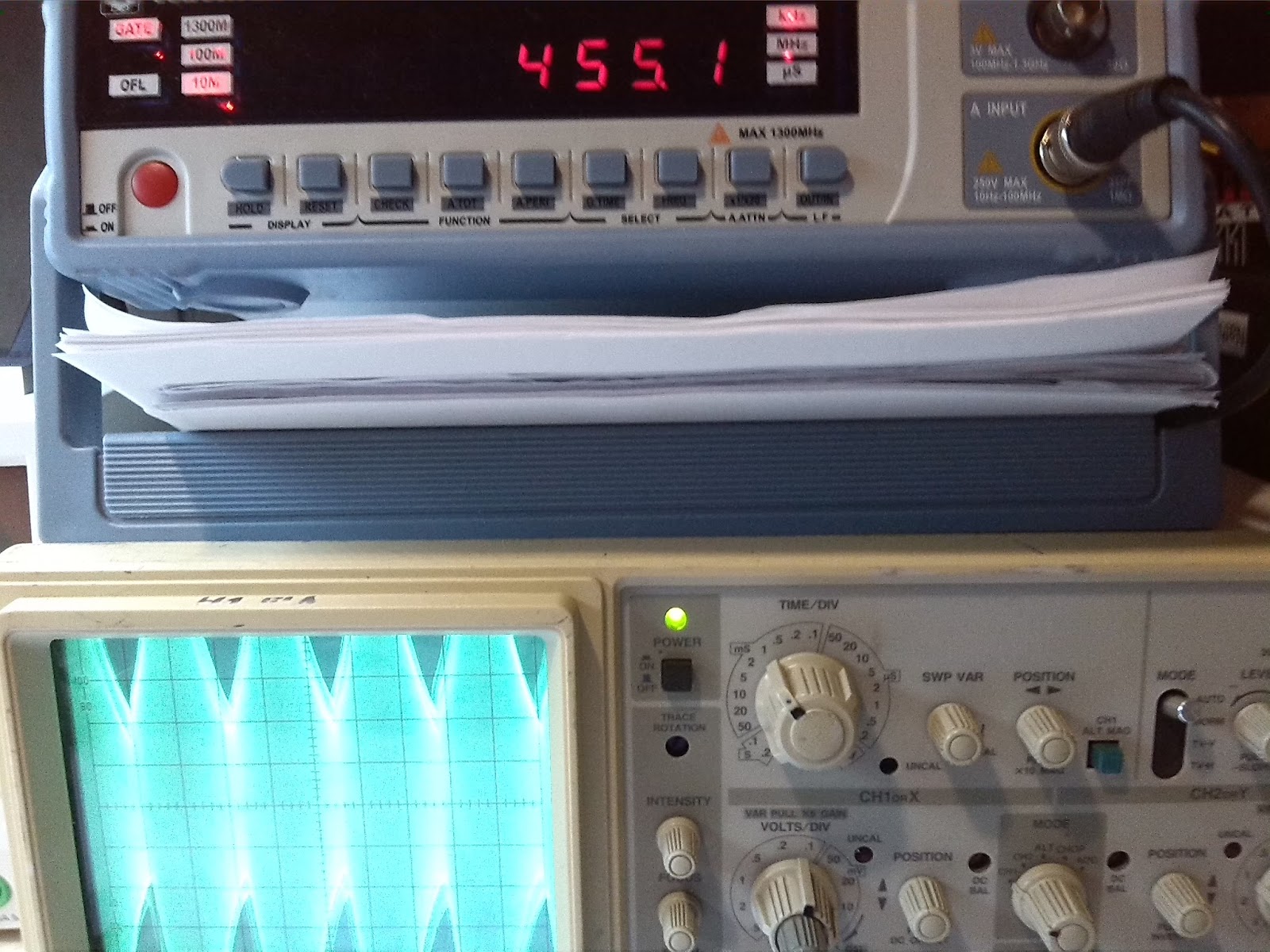 |
| Checking the carrier frequency is 455kHz The crystals are nominally 455kHz but are affected by capacitance and temperature. My frequency counter shows 455.1kHz which is good enough for me. |
 |
| My oscilloscope shows the 450Hz audible modulation on top of the 455kHz carrier signal. At 0.2V/div, you can see the signal is around 1.6Vpk-pk |
Copper strip board layout
The images below were created to help me visualize the layout of the schematic on copper strip board. they're here for reference if you want to use them. you could make the circuit a lot more compact, but as I previously stated, the aim was to produce a board I could easily follow with the schematic.
 |
| Top side - shows component layout and which strips have 9V, GND and ANTENNA |
 |
| Top side - shows 'ghost' of components and breaks and solder points from underside |
 |
| Under side - shows breaks and solder points |
I'm taking the same Elenco course and this project would help me get more out of the course and also provide a nice piece of test equipment for my electronics lab. I'm in.
ReplyDeleteHi, thanks for the comment.
ReplyDeleteI built this because, at the time, I didn't have a Signal Generator that would perform AM modulation. It's not perfect, but definitely helps tune the IF coils in the Elenco AM kit. Perhaps a really long coil of wire for the aerial would make it more effective.
I'd be interested to see your finished IF tester, so please post a link here to your pics if you put them online.
Please let me know how you get on building the Elenco AM kit. I had to wait months for the kit to be shipped here to the UK, but it was worth the wait. Clear instructions and good components (a lot better than the Chinese kits from eBay!).
I found some of the explanations in the instructions a bit technical, but the descriptions of how to test each section were excellent. The only assembly problem I had was getting the lead-free solder to adhere to some of the pads. a good clean with methylated spirit and the use of a flux pen helped.
I also ordered the Elenco FM kit but have held off building until I could afford better test equipment (some of the tests require specific AM and FM modulated signals). Now I have a cheap Chinese DSO and Signal Generator, I'll give that kit a go too!
Have fun!
I have just built one of these using the original circuit from Silicon Chip magazine.The only slightly different value component I used was a 25pF vintage capacitor. I agree that the LED and its resistor can be left out as it only is a power indicator. Even without an antenna I can hear the oscillation when I bring it close to a digital AM radio tuned to 455 kHz. Touching the radio's telescopic antenna with the antenna end of the 25pF capacitor allows the signal to be heard very strongly.
ReplyDeleteThanks for this! I just built one up with 2N2222 transistors throughout. It works very well for aligning old antique AM radios.
ReplyDeleteYou're Welcome! Please feel free to post links to the finished circuit if you have pictures on the Web.
ReplyDeleteHi can you tell me what type of capacitors are C4, C5 & C6?
ReplyDeleteAre C1 & C2 MKT types?
Could I use Ceramic Capacitors?
Thanks Paul
How do tune an aam radio to 455khz it's not there, starts at 550 if you go below you have no idea where your at, also where the output of this generator, why Leve such basic info an old idiot like me would like to have things simplified
ReplyDelete@Odf: Hi there. 455 kHz is what is called the intermediate frequency (IF) of a radio. Without going into great detail, 455 kHz is one of the most commonly used IFs used in the superhet radio. You will not be able to tune to 455 kHz on most radios and neither do you need to do so to use this signal generator. There are some methods to help you align your radio correctly. If you need further information, please reply. Regards.
ReplyDeleteI built this circuit using 2N2222A TO-18 package as Q3 and for antennae i used a telescopic type aerial and it works brilliantly can tune 455khz at around 900khz on am tuning scale here in NewZealand .
ReplyDeleteI built the circuit this morning in Manhattan style, I also use 2n2222's through out, nice clear tone, retune a old am radio , very nice circuit
ReplyDeleteI will recommend anyone looking for Business loan to mr benjamin who helped me with Four Million USD loan to startup my business and it's was fast When obtaining a loan from them it was surprising at how easy they were to work with.The process was fast and secure. It was definitely a positive experience.Avoid scammers on here and contact mr benjamin On. 247officedept@gmail.com . WhatsApp...+ 19893943740. if you looking for business loan.
ReplyDeleteI'm making a vacuum tube radio from scratch and this is a nice little circuit for doing alignment. I have made .zip file that contains the gerber files in JLCPCB compatible format here:
ReplyDeletehttp://kingsmills.us/Radio/Signal%20Generator/
Modern miniature LEDs can be obnoxiously bright at only 1 or 2 mA, so their power need not be a concern. It seems that the smaller they are, the more intense they are, likely due to higher current density.
ReplyDeleteHow to change the output frequency of this oscillator to 460 khz
ReplyDeleteThanks for the inspirational blog and circuit. I chose to use a twin T oscillator circuit and a BJT in cascade as a modulator to the Pierce oscillator and arrived at the same place you did. This is a very handy piece of equipment for restoring vintage tube radios.
ReplyDelete